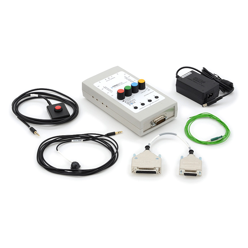
The g.TRIGbox is a device that generates trigger pulses from various sensors or input signals. Input and output lines are isolated from each other. The trigger outputs can be connected to digital or analog inputs of a data acquisition system (such as g.USBamp, g.HIamp, g.Nautilus).
Thus, g.TRIGbox provides precise detection and recording of almost any type of stimulation in your experimental paradigms. With its wide range of possible input signals and sensors, you can use various trigger sources such as sound card outputs, microphones, piezoelectric or inductive sensors, response buttons, various logic signals (TTL, C-MOS, …) provided by external stimulators, visual markers from the computer monitor, LED indicators, strobe lights, or slide projectors. The threshold levels are adjustable separately for each channel. 4 LEDs indicate the proper detection for each channel.
| Simply use PowerPoint for stimulus/paradigm setup and presentation |
| > 4 kV isolation between trigger inputs and outputs |
| Use various trigger sources from visual, auditory, electrical or tactile stimulators |
| Connect to a data acquisition system, g.HIamp, g.Nautilus or g.USBamp |
| Compatible with many other user-specific systems |
| Use one encoded trigger channel for up to 16 different experimental conditions |
| Trigger output voltage | TTL +5 V, BSL 200 mV |
| Input voltage (low level) | +/- 0,5 mV to +/- 200 mV (4 inputs) |
| Input voltage (high level) | +/- 100 mV to +/- 5 V (4 inputs) |
| Trigger output duration | Min. 20 ms |
| Supply | 9V battery or power supply |
| Current consumption | ~ 40 mA |
| Low battery indicator | ~ 7 V |
| Isolation voltage | > 4 kV (input/output) |
ROBOTIC CONTROL
If you want to control a robotic system with a steady-state visual evoked potential (SSVEP) based BCI, use the g.STIMbox and connect 4 LEDs. Then, define 4 different stimulation frequencies for the LEDs. We recommend avoiding the alpha region, because the alpha rhythm is often stronger than SSVEP signals in that frequency range. It is recommended to choose frequencies that are not multiples of each other (such as 8 and 16 Hz). For example, you might use 14, 16, 18 and 20 Hz for your four stimulation frequencies.
Use g.HIsys to acquire the EEG data from electrodes placed over the visual cortex and to analyze the SSVEP signals. Then, calibrate the BCI system by instructing the person to look at each LED a couple times while focusing on that LED After the calibration, the 4 LEDs can be used to move the robot forward, backward, left or right. To design a visual evoked potential (VEP) experiment, just connect a strobelight or similar device to the digital output and connect one digital output to the biosignal amplifier to have an exact trigger between the EEG data and the flash. Then use g.HIsys to extract, visualize and store the VEPs.

EXPERIMENTS WITH CRIMINALS
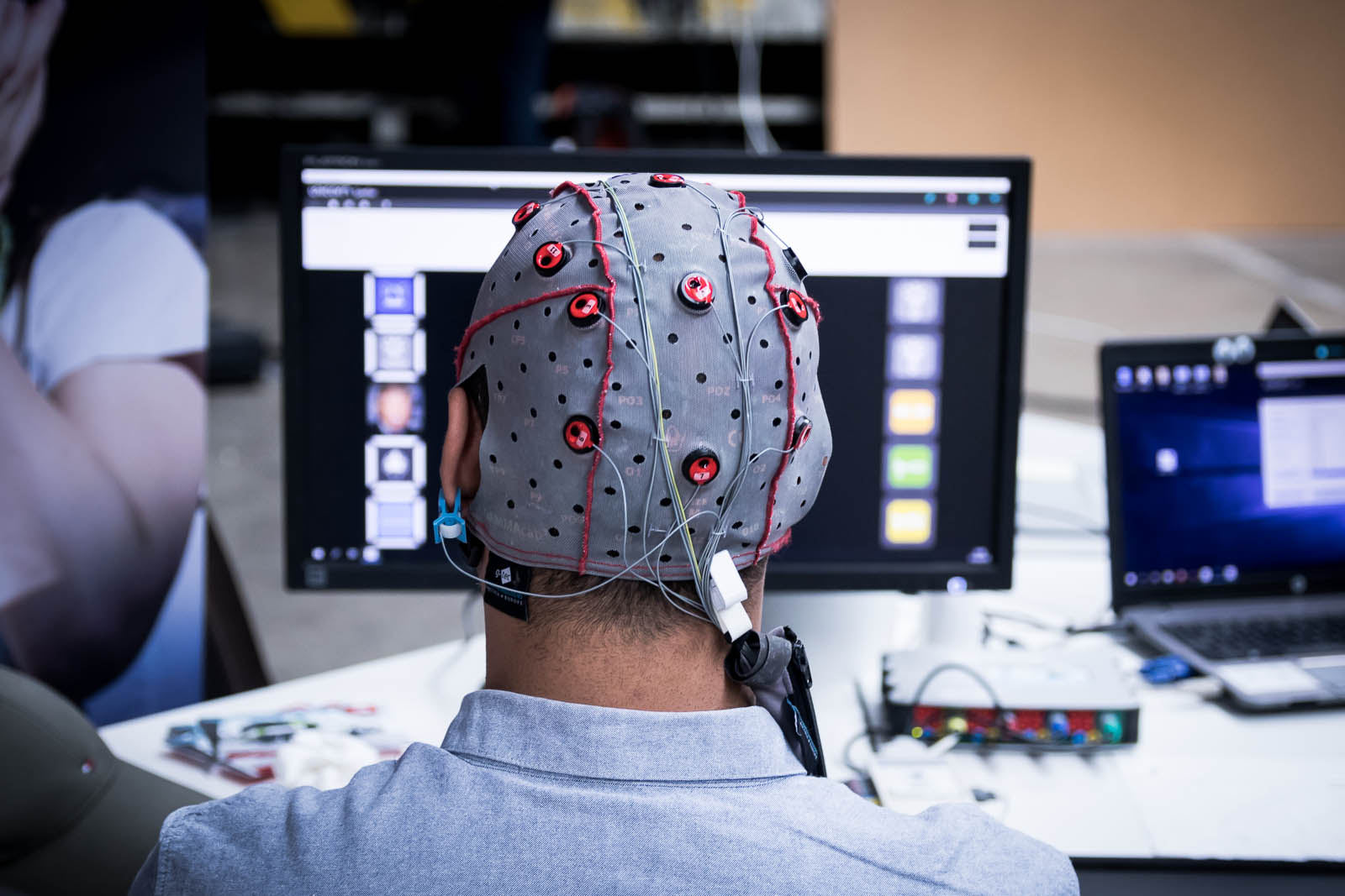
A P300 experiment to identify a “criminal” can be set up pretty easily with the g.TRIGbox. Create a PowerPoint presentation with 50 images of people that the criminal might know (targets) and people that the criminal will not know (non-targets). You should have about five times more non-targets than targets. Put the visual sensor on the screen to precisely detect the slide transition (put little markers in the PowerPoint slides in black and white). The g.TRIGbox will generate a TTL pulse whenever the slide is changed. This pulse is sent to the biosignal amplifier and recorded along with the EEG data. The real-time system can calculate EPs of all the target-images and compare it with the non-target images. The biggest P300 will be visible for the target images that the criminal knows.


NEED MORE INFORMATION
ABOUT THIS PRODUCT?
Send us your email so we can contact you as soon as possible.


