The g.HIsys Highspeed Online Processing for Simulink lets you collect biosignal data like EEG, ECoG, EMG, EOG, fNIRS and ECG within a Simulink model for further real-time processing and is available for g.HIamp, g.USBamp and g.Nautilus. Therefore, the device driver blocks for these devices are copied into the Simulink model and are connected to other blocks that do the signal analysis. Then, the model is started, and the device driver guarantees real-time processing.
This Rapid Prototyping environment speeds up the development cycle dramatically, and your first real-time experiments can begin within a few hours. g.HIsys allows you to use all standard SIMULINK blocks in your model and to write your own blocks in MATLAB or C.
The device driver block gives you access to all amplifier specific settings like sampling frequency, digital I/O lines, bandpass and notch filtering. Just double-click the Amplifier block to perform the settings. Then, click on Play in the SIMULINK model to start the biosignal acquisition. Additionally g.HIsys comes with many useful blocks for pre-processing, transformation, analysis and storage.
Data can be visualized with Scope blocks and stored on the hard disk in MATLAB format. The model works with double precision accuracy.
| Acquire and process EEG, ECoG, ECG, EMG, EOG, fNIRS and spike data directly within Simulink |
| Wireless biosignal data acquisition with g.Nautilus |
| Add your own sophisticated data processing algorithms graphically |
| Benefit from the Rapid Prototyping environment for developing, testing and releasing your biosignal applications |
| No compilation of the Simulink model is necessary for real-time analysis |
| Use standard Simulink blocks for online analysis |
| Add your own algorithms, such as MATLAB S-Functions or C S-Functions |
| Store data to the MATLAB workspace or to a MATLAB file |
| Display Evoked Potentials in real-time |
| Acquire eye-movement data together with biosignals |
| Create closed-loop experiments with g.tec’s stimulators and switching unit |
| Use the g.tec toolboxes with ready to go applications |
| Use g.CUBE for perfect audio stimulation, vibro-tactile stimulation, FES and tDCS stimulation |
| Map cortical activity to 3D models |
“The g.tec g.HIsys environment allows my lab to rapidly develop new applications. Biomedical engineering students here at Columbia University use the rapid prototyping environment during their education to get familiar with data acquisition, real-time processing and signal analysis.”
Nima Mesgarani, PhD - Columbia University, New York, USA
BASIC 950,00 €
Buy with a g.HIamp, g.Nautilus or g.USBamp to save 5%
- Amplifier block to read data from g.USBamp, g.HIamp and g.Nautilus
- Scope for ultra-fast raw data visualization of up to 1024 channels
- Full control of biosignal amplifiers
- 1 Block Library
- 5 Simulink Models
- Onboarding
PROFESSIONAL 4.950,00 €
Buy with a g.HIamp, g.Nautilus or g.USBamp to save 10%
- Amplifier block to read data from g.USBamp, g.HIamp and g.Nautilus
- Scope for ultra-fast raw data visualization of up to 1024 channels
- Full control of biosignal amplifiers
- 19 Block Libraries
- 118 Simulink Models
- 89 Signal Processing Blocks (Feature Extraction, Pre-processing, Visualization. Classification, Paradigm)
- P300 BCI (Visual P300, Vibro-tactile P300)
- SSVEP BCI
- Motor Imagery BCI (Bandpower, Common Spatial Patterns, Common Spatial Patterns with FES)
- Physio Observer
- g.Estim PRO and Switching Unit Interface
- g.Estim FES Interface
- g.STIMbox Interface
- Transcranial magnetic stimulation
- Eyetracking Interface
- UDP Interface
- Distributed EEG
- Cortico-Cortical Evoked Potentials
- ECoG
- Functional Near Infrared Spectroscopy
- Virtual and Augmented Reality
- Neuromodulation
- Evoked Potentials
- Audio, Video, Keyboard, Mouse
- Hyperscanning
- EMG/EOG control
- ECG and respiration
- Hybrid BCI
- Remote Data Acquisition Block
- 3D Visualization
- LSL interface
- Central sulcus mapping
- g.CUBE interface
EYETRACKER INTERFACE
The Eyetracker Interface for Simulink allows you to acquire eye gaze and x-, y-coordinates of the eye together with biosignal data. The signals can be visualized, stored and analyzed in real-time in SIMULINK and offline in MATLAB. The Eyetracker Interface for g.HIsys allows users to acquire biosignal data such as EEG, ECG, EMG, eyetracking information, and other signals in real-time. It provides a block to read gaze data from the eye-tracker simultaneously with other biosignal data coming from g.USBamp, g.HIamp or g.Nautilus wireless EEG system with dry or wet electrodes.
g.ESTIM PRO INTERFACE
g.tec provides an intracranial stimulator with 80V compliance voltage for electrical stimulation of the cortex with ECoG grids or strips or for depth electrodes. This can be used e.g. to stimulate the sensory cortex to add a touch feeling if robotic devices are controlled with the BCI or for deep brain-stimulation experiments e.g. with Parkinson patients. Stimulation parameters such as on-set time or stimulation current can be set and triggered in real-time from Simulink. Use the switching unit for 256 channels to select the channels that should be stimulated. The switching unit can be controlled in real-time directly from g.HIsys.
UDP INTERFACE
The exchange of data between different computer systems is important for many applications. The UDP Interface for MATLAB/Simulink provides ready-to-use Simulink blocks and MATLAB functions to transmit data from a biosignal recording device to other applications like a Virtual Reality system or another MATLAB instance on another PC. The UDP Interface can be used to exchange data between 2 Simulink applications running on two different PCs or notebooks.

DISTRIBUTED EEG
The Distributed EEG allows you to record biosignal data using the g.tec amplifiers from different distributed PCs (Data PCs) in the network and transmit the recorded data to a central evaluation / data storage PC (Eval PC). Data acquired from the Data PCs are synchronized using the OSC protocol for distributed systems, and the data are transmitted to the Eval PC using the UDP network interface.
g.ESTIM FES INTERFACE
The g.Estim FES Interface allows you to set all required parameters of the FES stimulator and to trigger the stimulator from Simulink. Importantly, the stimulator also measures the stimulation current to confirm that the actual current can be delivered (depending on the electrode impedance). The g.Estim FES Interface provides a graphical interface to the g.Estim FES hardware, which can be used under Simulink to specify the properties of the electrical stimulator.
The Simulink block allows you to specify the Phase Duration, the Phase Amplitude in real-time or via a graphical user interface and allows to start and stop the stimulation. The block provides the state (on/off), the battery level, the Max. Phase Duration and the Max. Phase Amplitude to the user. Use the FES Control Panel to manually set the stimulation parameters and to start and stop the stimulation. The applied charge density is also visualized in the window.
RUN EXPERIMENTS WITH EEG AND FNIRS
g.HIsys includes a toolbox to record and analyze EEG and fNIRS in real-time. This is done by adding an Amplifier block to record from g.USBamp, g.Nautilus or g.HIamp and by adding the fNIRS block. The Amplifier block is running with a high sampling frequency as the fNIRS block and defines therefore the update rate of the Simulink model. In Simulink both, the EEG and the fNIRS data streams can be visualized, processed and stored.
MOVEMENT CONTROL
The Simulink model can read in 16 EEG channels. The data are converted to double precision and a CSP filter is applied to perform a motor imagery BCI analysis. Then, the data are bandpass filtered and the variance of the most important CSP channels is calculated.
Then, the data are normalized and classified to provide a feedback output to the BCI user. If the subject imagines a right or left hand movement and the BCI detects it correctly, then a FES stimulation of the right or left hand is performed. The BCI Paradigm block controls the experimental procedure. The data are stored in MATALB format.
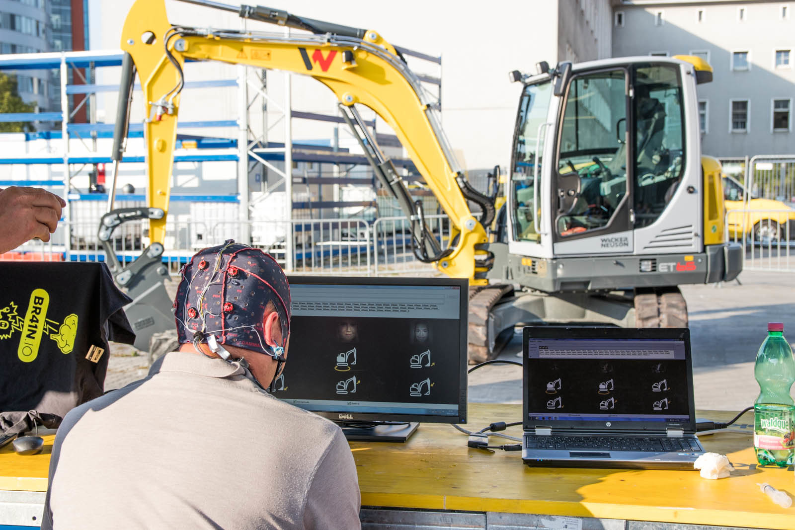
EXCAVATOR CONTROL
During the Ars Electronica Festival, g.HIsys was used to control the movements of an excavator! Visitors could use their P300s and related signals to direct the excavator. The BCI system was calibrated with 5 min EEG data in g.BSanalyze and the g.HIsys used this information to make a real-time decision about the users’ intent.
ECOG TOOLBOX
The ECoG toolbox allows to run experiments to perform a functional mapping of the cortex with high-gamma activation signals. The big advantage of g.HIamp in combination with g.HIsys is that the high-gamma signal can be recorded up to 1 kHz because of the superb noise-floor of g.tec technology. Normally these high frequencies are hidden because of amplifier noise, but g.HIamp uses a very high oversampling of the EEG data that is performed in two co-processor in the unit to reach this goal.

ACTIVITY MAPPING WITH THE BUBBLE SCOPE 3D
Use the Bubble Scope to examine significant activation of brain areas with a realistic representation of the implanted ECoG grids on the reconstructed patient’s brain in 3D. The Bubble Scope is part of g.HIsys Professional.
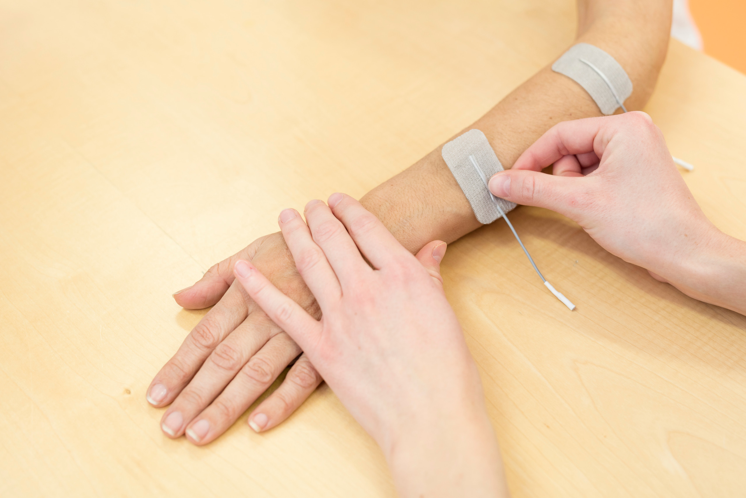
CENTRAL SULCUS MAPPING
In this video a patients’ hand receives vibro-tactile stimulations while the ECoG is recorded and analyzed. The EP scope shows the evoked potentials coming from the ECoG signal and the phase reversal between the sensory and motor cortex which defines the central sulcus. Of special importance is that just a few stimuli are needed to produce the result because the noise floor of the equipment is very small because of the high oversampling technique done in the g.HIamp.
EPILEPSY MONITORING
In this video g.HIsys is used to monitor an epilepsy patient with ECoG implants. The left scope shows the raw ECoG data recorded and the right scope show the high-gamma filtered ECoG. After a few seconds a seizure starts to spread out from the middle of the brain to all the recording sites. The bubble scope is use to show significant changes of activity and it shows very nicely the propagation of the seizure in real-time.
g.HISYS BLOCK LIBRARY
g.HIsys comes with specialized blocks for biosignal analysis that are needed in many real-time experiments. The library contains blocks for plotting data, pre-processing (source derivation, Notch filter, cascading Notch filter, bandpass filter), transformation (Trigger, Cut Samples, Select Channels), feature extraction (Moving Average, ERD, FFT, Pre/Post PSD, Spectrogram, Significance Analysis), output signals through muscle activity (Spasticity Control, EOG Selection, EMG Selection Threshold) and a Binary Decoder.

FILTERS
The source derivation, notch filter, cascading notch filter, EEG/ECG BW filter and BP BW filter blocks allow you to remove artifacts from the data or to extract certain components.
INPUT/OUTPUT
The Marker block is for keyboard and mouse markers in Simulink. The block checks the system for keyboard and mouse events and generates markers accordingly. Multiple blocks can be used to look for different events. The Mouse Pointer block can generate cursor movements via Simulink, similar to mouse control.
EXPERIMENTS
The Paradigm Presenter allows you to run multi-modal paradigms with videos, audio, text, images and DIO with g.STIMbox.
EXAMPLES
Examples contains many ready-to-go Simulink models.
EMG/EOG
Spasticity Control allows you to check the EMG contraction level, EOG Selection allows you to control a device with eye-blinks and eye-movements, EMG Selection Threshold calculates the RMS and allows you to trigger on muscle movements, EMG Selection Calibration allows you to calibrate on certain muscle movements to generate triggers if the threshold is crossed and EMG 2D selection calibration allows 2D muscle control.
FEATURE EXTRACTION
Feature extraction blocks allows you to calculate the power spectrum, ERD, FFT, averages and to perform a significance analysis.
AUDIO/VIDEO PROCESSING
The Audio Stimulation block presents a set of pre-recorded sound files via a low-latency sound driver to create different types of audio stimulation. The sound files can be enabled using a given sound ID. The Audio Stream block outputs stereo CD quality sound to the standard speakers from Simulink. The Camera Synchronization block allows you to record videos together with biosignals.
SIGNAL QUALITY
The EEG Quality Check and EEG Quality Display allow you to perform real-time artifact detection and to identify whether the data are clean during the experiment.
FILE IO
The Load Data Stream and Save Data Stream blocks are highly optimized for quickly streaming data, which is especially important for a high number of channels or high sampling rates (up to 38.4 kHz per channel). The blocks also allow you to define a maximum file size to avoid unnecessarily large data-sets.
VISUALIZATION
The Vector Scope allows you to visualize signal averages of multiple channels, the EP Scope can show EPs from target and non-target signals and perform a statistical analysis, the SCOPE is used to visualize raw biosignal data with markers and triggers and the Threshold Scope allows you to visualize biosignal data and manually define a triggering threshold. The Spectrum Rawdata Scope and Spectrogram Scope are used to visualize EPs and spectrum data. The 3D Visualization Bubble Scope allows to show activations of certain cortical areas, the 3D Interpolation Scope allows to map EPs/ERS to the head or cortex, the 3D Multi Interpolation Scope allows to show brain maps at specific time points and the 3D Data Quality Scope allows to show quality indicators like impedance on a head model.
SIMULATION
The Real Time Clock allows you to run the Simulink model without an amplifier connected and to simulate real-time behavior.
BATCH PROCESSING
The Automatic Batch Starter block allows to specify necessary off-line processing steps for a certain Simulink model. When the Simulink model is stopped, the processing is automatically performed.
SIGNAL MANIPULATION/TRANSFORMATION
The Select Channels blocks allows you to perform the signal processing steps on a sub-set of channels, the Cut Samples block is used for EPs to select a pre- and post-stimulus interval and the Trigger block allows you to select epochs for EPs. The Select Events block selects event codes from the incoming events. For each change of the incoming event code (from zero to a non-zero value), the event codes are compared to specified event codes for selection. The Binary Decoder converts data into binary format e.g. to generate trigger signals. The Sensor Adaptation block converts input data from a g.tec sensor (such as a temperature sensor, g.Sensor, GSR sensor and SpO2 sensor) into meaningful outputs corresponding to the sensor.
REMOTE DATA ACQUISITION
Acquire data from a remote g.NEEDaccess server.
LAB STREAMING LAYER
Use the LSL protocol to send data or to receive data.
TOOLBOXES
g.tec develops many toolboxes that run under g.HIsys. These toolboxes contain all real-time processing code and allow to interact with g.BSanalyze to calibrate BCI systems or to perform offline analysis.

REAL-TIME ANALYSIS
g.HIsys contains a biosignal processing blockset for use with Simulink. The blocks can be used for on-line simulations under Simulink and for real-time applications.
Drag and drop the pre-processing, parameter estimation and classification algorithms into your Simulink real-time application to accelerate your research, encourage creativity and reduce project costs. The blockset enables you to quickly compare multiple algorithms. Use the blocks as templates and make your own modifications.
The blockset is divided into general purpose blocks and biosignal processing blocks. General purpose blocks are derivations, filters and different algebraic blocks. Biosignal processing blocks are used for pre-processing, parameter estimation and classification of off-line or real-time EEG, ECG, EMG, respiration or galvanic skin response data.
MULTI-DEVICE ACQUISITION
g.HIsys also supports the acquisition from multiple g.tec amplifiers of similar or different type. This means a g.Nautilus can be used with a g.USBamp or g.HIamp, even with different sampling frequencies. You can also use multiple g.HIamps, g.USBamp or g.Nautilus in one single Simulink model. In Simulink, every amplifier is set up with a certain, individual sampling frequency. The amplifier block delivers the data samples in real-time to a Scope, to the signal analysis or to store the data. This allows you to work with more than 256 channels e.g. for ECoG studies, and it also allows you to record from multiple users at the same time on one single computer. This makes the online data quality control much easier, requiring only one computer for data storage that can analyze data from multiple users.
Included parameter estimation blocks are: Hjorth parameters, Barlow parameters, Bandpower, Variance and Adaptive Autoregressive Models with RLS, Kalman and LMS algorithms, Minimum Energy, EMG Coactivation Index and EMG Spasticity Control. All important methods for BCIs based on P300, motor imagery, SSVEP/SSSEP and slow cortical potentials are included. The ECG Time Domain Analysis block allows you to calculate heart-rate and heart-rate variability parameters. Furthermore, respiration rate/deepness and the change rate of galvanic skin response can be calculated. The blockset contains also blocks to control a system with EOG and EMG activity for human computer interaction.
The Apply Classifier block allows you to use linear and non-linear classifiers for the on-line classification of parameters. Examples are linear discriminant analysis or support vector machine based classifiers calculated in g.BSanalyze. The classifier block also performs a statistical analysis to realize a zero class for BCI control. This means that the BCI system will not make a decision if the subject is not paying attention. Furthermore, blocks for majority voting and change rate calculation are included.
CAMERA CAPTURE
The Camera Synchronization block allows you to record a video from a webcam in MATLAB/Simulink and to synchronize the video with the biosignal data. The synchronization is done using the video frame number, which is output from the Camera Synchronization block and saved with the biosignal data. The biosignals and video can be read with g.BSanalyze for offline analysis
3D VISUALIZATION AND BRAIN MAPPING
g.HIsys contains new 3D visualization scopes such as the Bubble Scope to map brain activation to certain electrodes. The Interplation Scope helps you to interpolate brain activation and to project it to the head or cortex. With the Multi Interpolation Scope you can easily show activation maps at certain time points. And finally, the Data Quality Scope allows you to map data quality parameters to the skull or the cortex such as impedance.

ULTRA-HIGH DENSITY BRAIN MAPS
Map cortical activity recorded with the ultra-high density EEG system g.Pangolin in g.HIsys Professional in real-time. The electrode locations are interactively defined with the g.Pangolin Montage Creator. This visualization can be used for standard EEG recordings, too.
g.CUBE STIMULATION PLATFORM
The new g.CUBE is a multi-modal stimulation unit that allows you to get real-time control of auditory, vibro-tactile, FES, tDCS stimulation.
- Auditory stimulation: enables the auditory stimulation of the left and right ear and sends perfectly aligned triggers to the EEG processing for suberp AEPs and BAEPS.
- Vibro-tactile stimulation: enables the vibro-tactile stimulation of up to 7 locations on the body and sends perfectly aligned triggers to the EEG processing.
- 2 x FES stimulation: enables the bipolar, biphasic functional electrical stimulation with 2 bipolar channels on two locations (e.g. hand and leg).
- 2 x tDCS stimulation: enables the transcranial direct current stimulation with bipolar electrodes on two locations on the head (e.g. motor cortex and frontal cortex)

PHYSIO OBSERVER
The Physio Observer is a complete system to classify different states of a subject based on physiological parameters. The system contains all necessary components to quantify emotions, workload, physical tasks and many other things.

The Physio Observer works with many different sensors and electrodes to measure physiological and physical parameters of a subject, and can derive a wide variety of parameters from these signals. A key feature of the system is that it allows you to run experimental paradigms that are synchronized with physiological signals. The paradigms allow you to bring the subject into specific states of emotions, workload, memory tasks, etc., while all parameters are captured. These states can be chosen by the experimenter. Then, a classification algorithm is trained on these parameters during the different states and tries to discriminate them. Finally, the accuracy is calculated, which provides an objective measure of the quality of the classification. The Physio Observer works in real-time, and can therefore track the current state of a subject on-line. This information can be transmitted to other applications or devices, including real-time feedback systems.
The Physio Observer is able to measure ECG, EEG, EMG, GSR, respiration, temperature, acceleration and oxygen saturation with g.USBamp, g.HIamp, g.Nautilus. This biosignal data is transmitted via USB or wireless to the recording computer that is storing and visualizing the data for inspection.
The recording computer also controls the experimental paradigm that instructs the subject about different tasks (e.g. calculating). The real-time processing system extracts parameters from the biosignal data such as heart rate, heart rate variability, respiration rate, inhalation time, change rate of GSR, etc. and classifies the data. Finally, the classification result predicts the subject’s current state. This result is updated in real-time and can also be transmitted to other applications or the experimenter.
The experimental paradigms are presented by default on a computer screen that gives the instructions to the subject. You can also use a head-mounted device, a Virtual Reality system from g.tec, or a custom exoskeleton system. Furthermore, the system can work with eye- and movement-trackers, to give tone, electrical or tactile stimulation. A microphone can be connected to log subject responses.
The UDP Interface allows you to send the classification result, and the calculated parameters, to other applications to support real-time loops.
| Train the Physio Observer with different tasks |
| Classifies physiological parameters in real-time to determine the state of the subject |
| Gives accuracy as an objective measure |
| Select from a large variety of different parameters |
| Send the classification result to other applications to execute closed-loop experiments |
| Measure ECG, EEG, EMG, GSR, respiration, temperature, acceleration and oxygen saturation with g.USBamp, g.HIamp, g.Nautilus |
| Record, store, visualize data |
| Real-time transmission to other applications or the experimenter |
| Addition of head-mounted device, a Virtual Reality system from g.tec, custom exoskeleton systems, eye- and movement-trackers, electrical or tactile stimulation |
| UDP Interface |
HOW TO USE PHYSIO OBSERVER
First, place all the electrodes and sensors on the subject. Then, start the experimental paradigm, during which the subject receives instructions from the computer screen and has to perform specific predefined tasks. Meanwhile, all of the subject’s biosignal data is acquired along with synchronization triggers.
When the paradigm stops, the offline analysis begins to calculate parameters. With these parameters, a classification algorithm is trained, which discriminates between the different states of the experimental paradigm and gives an accuracy level to quantify the separability. If the accuracy is not good enough then (i) additional sensors or electrodes can be used, (ii) the paradigm can be improved, or (iii) additional parameters can be added.
One good parameter for detecting mental counting is the bandpower of EEG data in the alpha region. When the accuracy meets the expectations of the experimenter, then the Physio Observer is ready for real-time tests. The paradigms are started again, and now the system gives a real-time prediction of the current state of the subject with a certain likelihood. The parameters, as well as the predicted state, can be sent to other applications. Finally, the accuracy can be calculated again to see if the system can discriminate the different states.
G.TEC SUITE 2020
The g.tec Suite 2020 contains all software packages from g.tec, such as g.NEEDaccess with all APIs, g.HIsys, g.BSanalyze and g.Recorder. It allows an easy installation, update and organization of all software packages, and comes with an automatic software compatibility check to minimize any software issues on your computer.
From now on, software upgrades e.g. from g.HIsys BASIC to PROFESSIONAL are made simple.

NEED MORE INFORMATION
ABOUT THIS PRODUCT?
Send us your email so we can contact you as soon as possible.


